Accurate, detailed, and well-organized shop drawings are the backbone of any successful HVAC project. These drawings are more than just blueprints; they act as a critical communication tool among contractors, engineers, and HVAC professionals to ensure flawless project execution.
If you’re an HVAC professional, contractor, or engineer, understanding the intricacies of HVAC duct shop drawings can make all the difference between smooth installations and costly errors.
This guide breaks down the key components of HVAC duct shop drawings, explores best practices for their creation, and discusses how technology is reshaping the industry. By the end of this post, you’ll have a clear roadmap for ensuring your shop drawings meet professional standards while optimizing project outcomes.
What Are HVAC Duct Shop Drawings and Why Do They Matter?
HVAC duct shop drawings are detailed construction plans tailored specifically for building HVAC systems. They provide visual representations and technical specifications to translate design intent into actionable, on-site instructions.
These drawings ensure that the ductwork installation aligns with architectural designs, complies with building codes, and avoids clashes with structural or electrical systems.
Why are they important?
- Precision in Installation: Shop drawings minimize ambiguities by providing clear, measurable details for fabricating and installing duct systems.
- Cost and Time Efficiency: They prevent rework due to errors or misalignments, saving both time and money.
- Streamlined Communication: Clear documentation ensures collaboration between designers, contractors, and field workers.
- Regulatory Compliance: Accurate drawings aid compliance with local and international HVAC standards.
Without high-quality HVAC duct shop drawings, even well-designed HVAC systems can face delays, conflicts, and inefficiencies during construction.
Essential Components of HVAC Duct Shop Drawings
An effective set of HVAC duct shop drawings includes a variety of components, each serving a specific purpose. Below are the key elements that every professional should master.
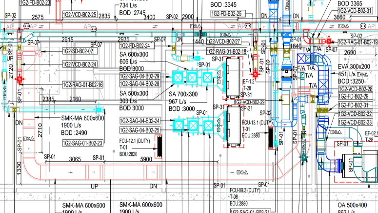
1. Plans
Plans are the bird’s-eye view of the duct system. They show the layout of ducts, equipment, and accessories as they relate to the building’s floor plan.
Key Details in Plans:
- Duct routes and dimensions.
- Locations of diffusers, dampers, grills, and registers.
- Coordination with mechanical, electrical, and structural systems.
2. Elevations
Elevation drawings show a side view of the system, providing critical vertical alignment information. This is especially useful in multi-level buildings or for coordinating above-ceiling installations.
Key Details in Elevations:
- Duct height and alignment in relation to floor levels and ceilings.
- Specific instructions for risers and vertical ducts.
3. Sections
Sections give a cross-sectional view of the duct system, zooming in on areas where precise detailing is required. They clarify how ducts interact with other elements within the building.
Key Details in Sections:
- Duct sizes and profiles.
- Insulation layers and materials.
- Clearance and spacing in tight areas.
4. Details
Details focus on specific parts of the system, such as joints, valves, fittings, and transitions. They ensure there is no room for misinterpretation during fabrication and installation.
Key Details in Drawings:
- Specifics for custom fittings like elbows, reducers, and offsets.
- Details on hangers, supports, and other hardware.
Each of these components works together to form a comprehensive set of shop drawings, leaving no room for guesswork.
Key Considerations for Accurate and Effective Drawings
Creating precise HVAC duct shop drawings requires thorough planning and attention to detail. Here are the top considerations to keep in mind:
1. Coordination with Other Trades
HVAC systems often share limited space with plumbing, electrical, and structural components. Effective coordination ensures that your duct system avoids conflicts with other trades.
2. Adherence to Codes and Standards
Ensure compliance with local building codes, ASHRAE guidelines, and project-specific standards. This guarantees that your installation passes inspections without delays.
3. Simplified Duct Configurations
Where possible, simplify duct designs to reduce fabrication complexity, material waste, and installation errors. Straightforward layouts often lead to better project outcomes.
4. Accurate Sizing and Load Calculations
Improperly sized ducts can cause insufficient airflow or excessive energy consumption. Perform thorough load calculations to determine exact duct sizes and specifications.
5. Consistent Labeling and Notation
Clear and consistent labeling helps installers quickly identify components during construction. Use standard nomenclatures and avoid clutter in your drawings.
By keeping these factors top of mind, you can create shop drawings that not only meet project needs but also enhance overall efficiency.
Common Mistakes to Avoid in HVAC Duct Shop Drawings
Even experienced professionals encounter pitfalls while creating shop drawings. Here are some of the most common mistakes and how to avoid them:
- Neglecting Collaboration: Failing to incorporate inputs from other trades can result in costly on-site adjustments.
- Overcomplicated Designs: Complex duct paths might look impressive but can lead to unnecessary material use and installation delays.
- Ignoring Scale and Proportion: Skewed or inaccurate scale in drawings can cause serious errors during fabrication.
- Lack of Clear Annotations: Unclear notes and missing legends can confuse installers and delay the installation process.
- Missing Elements: Omitting integral components like insulation or dampers can compromise the performance of the system.
Staying vigilant against these mistakes can elevate your shop drawing game while saving significant time, effort, and money.
The Role of Technology in Modern HVAC Duct Shop Drawings
Gone are the days of manually drafting shop drawings with pen and paper. Technology has revolutionized the process, making it more efficient and collaborative.
Software Transforming HVAC Drawings
- AutoCAD: A popular tool for creating 2D and 3D HVAC designs with pinpoint accuracy.
- Revit: Ideal for Building Information Modeling (BIM) to coordinate across disciplines.
- HVAC-specific plugins: Tools like Trimble’s AutoBid Mechanical streamline the shop drawing process.
Benefits of Digitization
- Improved Collaboration: Cloud-based software like BIM 360 allows teams to collaborate in real time.
- Error Reduction: Automated clash detection prevents unnecessary conflicts.
- Time Savings: Pre-loaded templates and libraries speed up the drafting process.
By incorporating these technological tools, HVAC professionals can improve accuracy, decrease turnaround time, and achieve superior project outcomes.
Why Accurate Shop Drawings Are the Cornerstone of HVAC Success
Accurate and well-thought-out HVAC duct shop drawings are not just a formality; they’re the roadmap to a successful HVAC project. By mastering their components, avoiding common mistakes, and leveraging modern technology, HVAC professionals can streamline their workflows and enhance their value in today’s competitive market.
Whether you’re a contractor, engineer, or facility manager, implementing best practices in your shop drawing process will drive better results and ensure lasting success.
Need to sharpen your skills or explore new tools for creating top-tier HVAC duct shop drawings? Get started today by exploring cutting-edge software solutions or collaborating with expert drafting teams.
Author: CAD Drafting Services
CAD Drafting offers architectural services such as CAD drafting, BIM modeling, 3D rendering, 3D modeling, shop drawings, CAD conversion, etc. 45+ team of COPL has the professional experience to provide these services for USA, UK, Canada, and Australia-based projects.

